Blog Archives
Hobbed Extruder Bearing
friend an I were putting together an extruder and a thought came through our heads. Why not hob a bearing for added traction? The bearing im referring to is the bearing in the extruder that pushes against the filiment for feed and retraction. Traction on both sides of the filiment surely would make some difference in the overall scheme of things. The hard part is trying to hobb a bearing. I’ve seen ones in the past that have a half circle like groove which help with alignment.
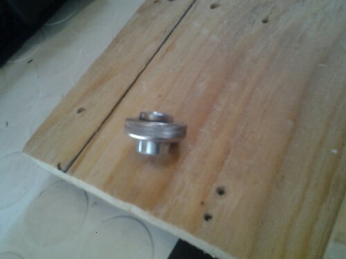
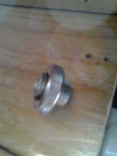
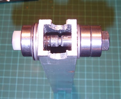
So I went about making a groove in a bearing as well as hobbing it. I used a customized bearing that my friend had made just for this part of the extruder. He had these bearings made with a lip on either side to sit perfectly in the door of the extruder so no piece of all thread is needed. I took some pictures but the camera on my tablet isn’t the best. I will try and get better pics in the future. I have yet to try it out but I will update as soon as I do.
Owens posted this to me:
The Steve’s Extruder that SeeMeCNC uses on some of their printers is set up with two hobbed pulleys on parallel shafts, both driven by a rather complicated gear train. I have no idea whether it works better or worse than what we use, though they are apparently happy with it. I’ve also seen pictures of a prototype extruder with a driven hobbed bolt and a hobbed pulley as idler, but I can’t remember where.
My response was this:
It would make sense that hobbing on both sides will increase traction, intern would help with alignment and make extrusion/ retraction more consistent. See me cnc has always been on the cutting edge of parts and I’ve heard very positive responses about their extruders. I plan on making several variations of this setup to see if their is a combination that will improve extrusion. This is something I will test on a custom bowden setup as well. Bowdens are known to have retraction issues. My overall goal is to make a reliable bowden setup that helps eliminate or reduce the downfalls of a bowden setup.
Hodge Podge Bolt Hobbing Mechanism
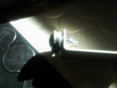
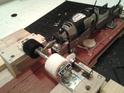
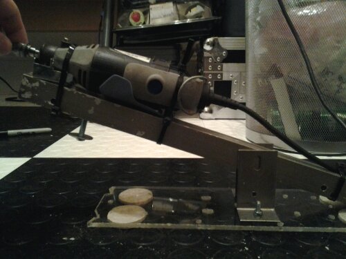
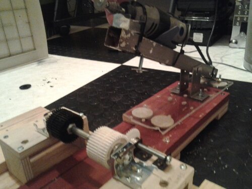
I decided that I wanted to experiment with different hobbed bolts with some kind of repeatability. So I dug in my scrap heap and came up with this. To make it I used scap plywood, metal tube, corner braces, nuts, bolts, plexi scraps, gears from a printer, blinds clips, dremel, a hinge and some l brackets. The gears are used so I can accurately determine rotation. The hinge work to cut accurately and I also fixed a washer and bolt under the dremel mount so I can adjust for depth. I have yet to try it out yet as I will get time later on to do so.I thought I would post it on here and maybe give some people some ideas for future scrap builds. I’ll update once ive made some hobbed bolts. Im currently messing with different cutting ends and techniques to determine what kind of hobbed bolt etc I want to make.
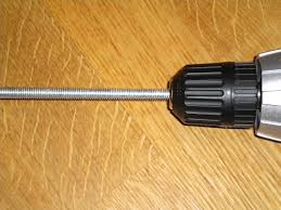
figured I would add how the groove is made before you cut the teeth. It can be made several ways. The way that ive found most convenient for me is to put the bolt or all thread rod in a chuck of a drill. I use to bearings to keep it in position much like you would do if you are tapping the bolt. I have one person hold the drill while I hold a file in the location ive determined to hobb. One person will give power to the drill so that it spins away from you and the file. Make sure you hold the file tightly in one location so it doesn’t skip around. Continue to file to desired depth. Note: I use a round file that is about 3-4mm in width and it has worked well for me in the past. It comes down to personal preferences. Also I highly recommend practicing because without practice more thqn likely you will mess up your first few times. After you have done this then you will be ready to cut the grooves using a dremel, tap, lathe or other tool of preference.
