Blog Archives
RepRap Squad’s Project Elsa i9
So we have decided to take on the Mendel 90 hybrid build as a side project as if we don’t have enough projects going on. We are not going to build a standard Mendel 90 however. We originally couldn’t decide between the Prusa I3 and the mendel 90. So we figured why not have our cake and eat it to. So after looking at plans for both designs we realized how similar they really are. We liked the I3 for some parts and the M90 for others. So we are going to take the best from each design and integrate them together while adding in a little of our own tricks as well. I will be updating as we go. So far the parts that are decided are the frame, z-motor mounts and top rod mounts. We are going to use the Mendal 90 frame with a few small adjustments. The I3 Z-axis motor mounts will be used as well as a variation the I3’s Z-axis top rod mounts. That’s all that’s been decided so far.
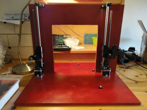
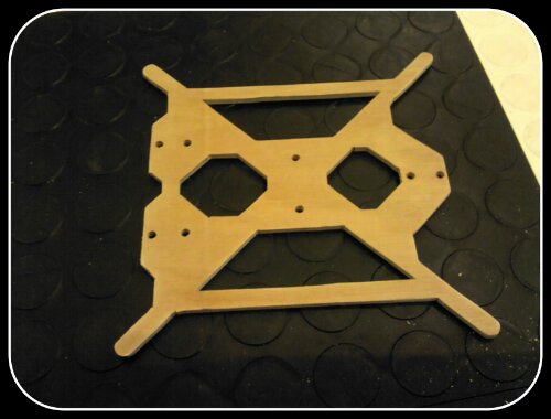
This is the Y-axis setup we will use from the I3
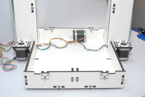
This is the frame basic design we will use:
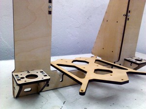
Here’s the motor mounts that will be used:
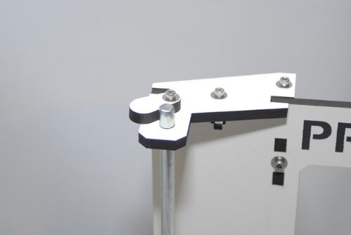
And here is the z-axis rod top holders that will be used as well:
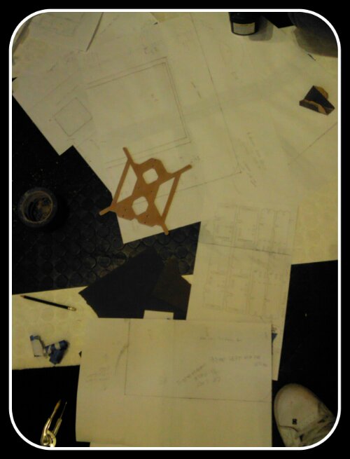
I’ve started sketching up rough plans so I can figure out what parts from each machine I’m going to use. I also have to figure out how to integrate them seamlessly so they work together and not against one another. I’m also figuring out parts that I will be custom building from other ideas and designs we have in the RepRap Archives. Luckily I have the better part of all the designs RepRap Squad has put together over the last few years. So it will be a matter of finding and adapting ones that are made for this design. I’ve been working non stop for the last week on design changes and my desk has been overtaken by models etc. So I have moved to the only feasible place with more space, the floor. Below you can see a small portion of my soon to be rats nest of ideas and sketches. I’ve made a quick mock up of the bearing mount for the Y-Axis taking design ques from the Prusa i3. After asking a few members for a working name for this project instead of calling it a mendel 90 Prusa i3 hybrid. We came up with the name Elsa i9. The name derives from the last two letters from the Prusa and the Mendel. The ‘i’ comes from Prusa and the 9 comes from the mendel 90. So it makes since and is a lot easier to reference. So from now on this project will officially be referred to as project: Elsa i9. As designs are confirmed I will post updates.
Update April 5th 2013–»
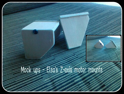
I’ve started smacking mock up motor mounts so I can figure out the best way to build them. I will be posting pictures soon. So far I like the motor mount design. The basic design was adopted from the Prusa i3’s motor mounts. I’m still trying to figure out if I want to use the tab system found in laser cut birch. After the Elsa i9 build is completed I will be making the majority of it out of acrylic or Dibond. Dibond is great because its strong like aluminium but weighs less and is easier to work with. The 1st version will be made up of birch. Motor mounts, Y-axis box frame, rear supports and top Z-axis supports will more than likely be made from a 6mm birch or similar wood. The reason I am going to use this kind of wood is because the 1st version will be a prototype that will have a lot of overall changes to it. That way we can get the design down and make it exact before we make the Dibond or acrylic final version. I was going to use the See Me CnC style Prusa boxed Y-axis frame but after looking at the design thoroughly we decided it would be better to make our own design that would fit the platform perfectly. So far that’s where we are at so check back soon for more updates as they come.
Update: April 7th 2013—»
After cutting out the mock-up frame I noticed that it seemed a little small. Even after having drawings I made to scale the Z-axis seemed too short. I was happy with what I had to work with for the X and Y-axis’s but the Z-axis seemed like it had more to offer me. So I am working on some Z-axis extensions that I will design specifically for this application. As of now my first thought is to make something different, something adjustable that will offer great support. Right before cutting I decided to go with a thicker base and a thicker front U frame. The supports in the rear will be 6mm birch as well as the motor mounts and framed y-axis bed. This will make it a little heavier but it will add strength where its needed. The motor mount mock ups version 2.0 look like they will work well. I am still experimenting with different ways to join the edges of the different pieces of birch. I might go with a variation between dovetailing and the laser cut style of joining.
Update April 7th 2013—»
We have been hard at work today working on the mock up design. Most people ask me why I don’t do everything in solid works or another design program first. The reason I don’t design it first is because a lot of the design has already been done for me thanks to Nopehead and Prusa as well as many other derivatives. With a lot of my builds I like to make a mock up version out of wood. Problem solving when building this way has always worked out well and I was taught old school as well. The mock up is going great and we have the majority of the frame together minus the Z-axis frame extensions. I will update soon but right now I have a lot more work to do. I finally got around to getting a few pictures of how the mock up looks so far. Remember this is just a mock up. The final design will have a lot of eventual changes. I like the way everything is coming together.
Here are some of the mock up photos I’ve promised you:—»
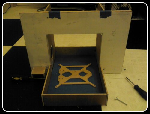
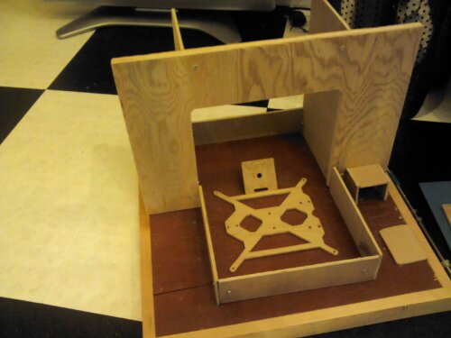
Above photo: The basic mock up frame
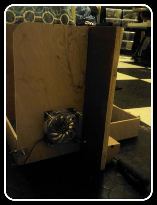
Above is the side mounted 60mm fan
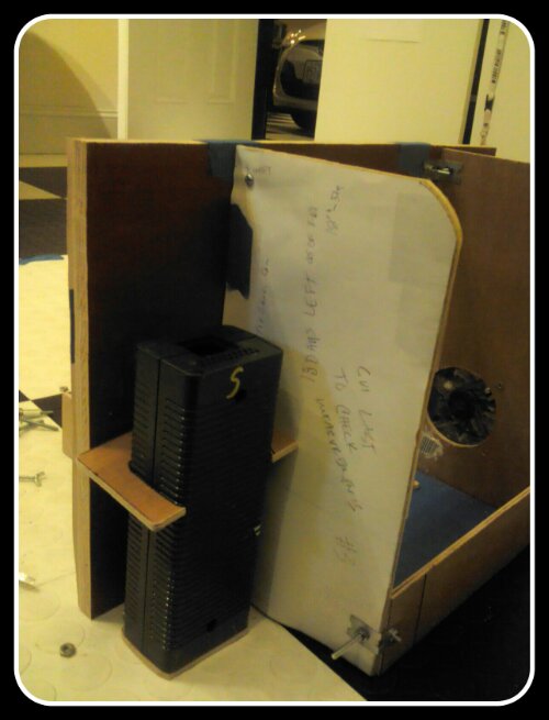
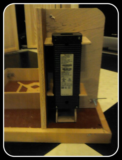
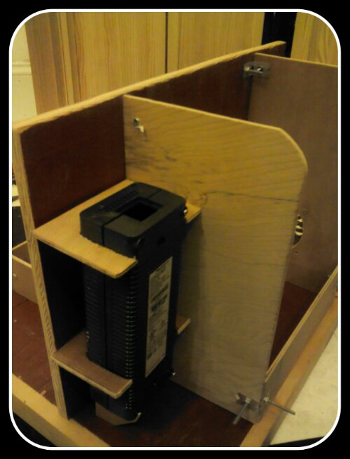
Above photo: I still have to make another one of the brackets like you see here to mount the Xbox power supply away from the wood which will help with cooling.
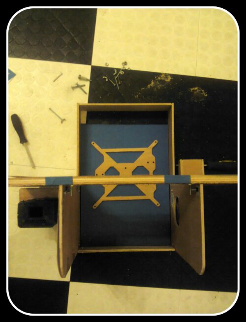
Above photo: Here you can see that I moved in the rear supports as well as adapted the prusa’s bed foundation.
Update: April 8th 2013—»
Today we started building the frame the Elsa will sit on. Instead of just cutting out a sheet of mdf we decided to build an actual, “frame” with supports. Underneath Elsa’s platform there is ribbing every 3 inches to make sure it is completely uniform. We also started building the mounts for our Xbox power supply. We have played around with a couple different mounting positions as you can see in the pictures below. Luckily we remembered to take the power cable into consideration. The power supply we have chosen is one we have used before with great success. The 203watt 16.5 amp Xbox power supply. There is also a post on this site describing how to mod it for reprap use. We all decided that we wanted to figure out a better way of routing cables and organizing them within this build. I asked that we try and take a fresh look at building Elsa while still taking into consideration the great designs that so many before has done. Including Nopehead, Prusa and so many more. This project will consist of a lot of design, building and redesigning and building. We now have a few more members of the RepRap Squad’s team joining the battle. So this should make for a great evolution of multiple designs as well as designers and input given from around the world. Well I promised you updated pictures so here is the rough mock up and the stage in which we are at.
Above pictured: Here we are trying to determine the final position of the PSU.
Above pictured: Another possible PSU location.
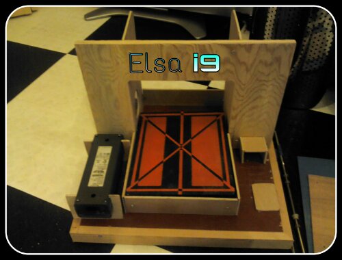
Above pictured: Another possible PSU location as well as the basic mocked up Y-axis and bed platform.
Above pictured: The basic skeleton of Elsa’s platform
Update April 9th 2013—»
Today we mostly worked on placement of electronics and wiring. I decided to print a female coupler for the Xbox psu plug, that way wiring would be more clean. I also made the mock up mounts for the Xbox power supply. My friend thought that it needed a little pazazz so he added LED lighting that you can see in the picture below. I also started to build the fan and filtering system. The fan located on the side of the print bed will pull in air and run it through an exhaust duct that will filter the air and expel the clean air. This is primarily for printing ABS and it may eventually be hooked up to longer duct work that will be piped into the exhaust system. All in all its starting to come together fairly easily. We are still trying to figure out the Y-Axis platform and how it will function.
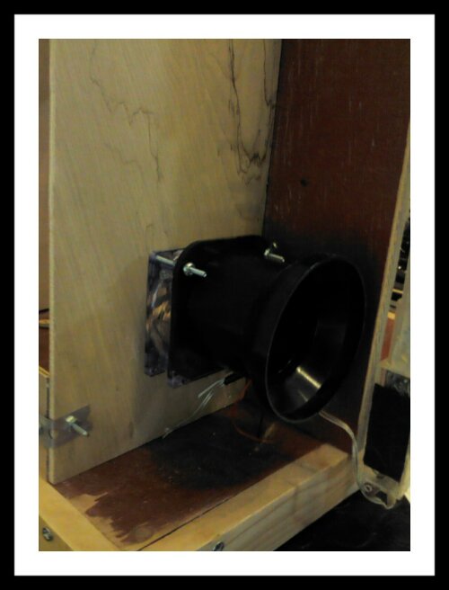
Above picture: The duct attached to the fan
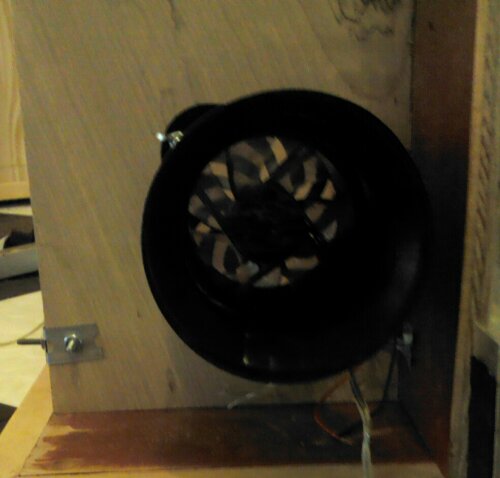
Above picture: Here you can see the inside of the exhaust tube.
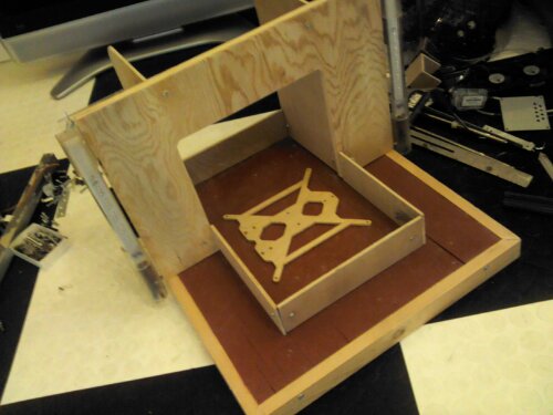
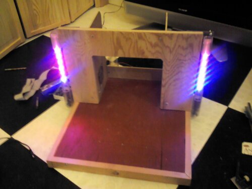
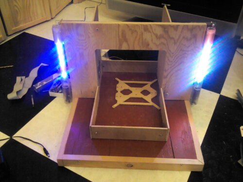
Above picture: Here is the LED lighting accents. Not sure if they will stay.
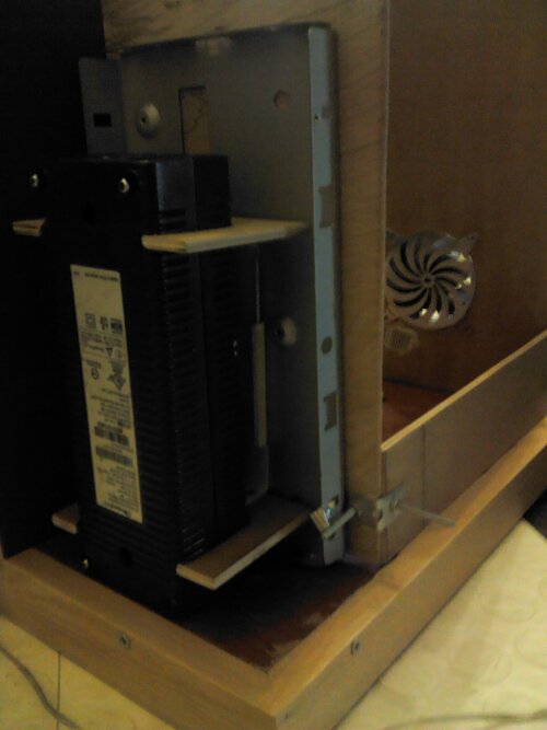
Above picture: Here is the PSU mock up location that will more then likely be the resting position of the power supply.
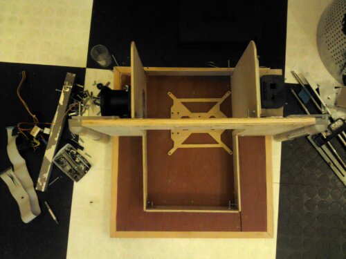
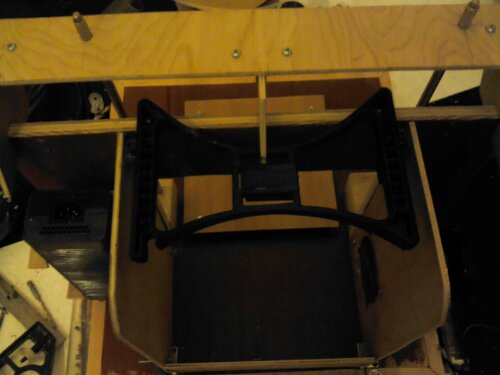
Above picture: Here is an above picture of the Elsa i9 ( Nothings bolted down to the base yet.)
Picture below: This is for Jace. He says that he likes the LED lighting on the side of the platform. I haven’t decided if I want to integrate it though.
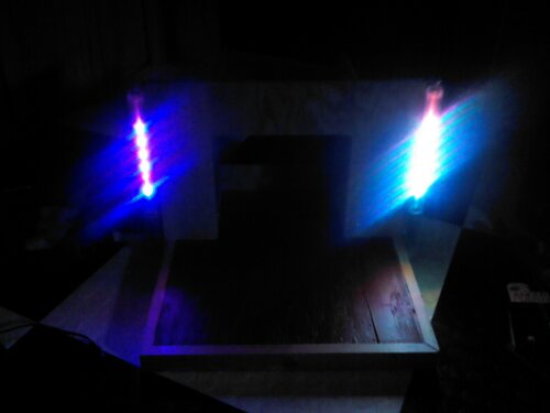
Update: April 11th 2013—»
We didn’t work on the project as much as we wanted to today due to outside interferences. However we did get the mock up for the z-axis extension done and they really add a good look to the platform. We are also starting to ween away from the framed Y-axis bed. So far we’ve decided to take out the front 3 pieces and it seems to look better. We are in the midst of making our mock up smooth rod holders as soon as we get exact dimensions. The mock ups for the z – axis, ( top & bottom) are almost done and they just need some design changes for aesthetics. After that they will be done. The LED’s have been temporarily been moved to the lower left and right sides of the base frame. I posted a few quick pics to show what we’ve changed as of today. I can’t wait to get the mock up stage completed so we can order the dibond and have it milled to specs. We are quite away out from that point but I know it will look amazing. We are making the z-axis extensions as an add-on able upgrade as of now. They are being engineered so that this will be possible even to existing mendel 90’s. Check it out and let me know what you think.
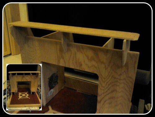
Above picture: z-axis extensions and y-axis change.
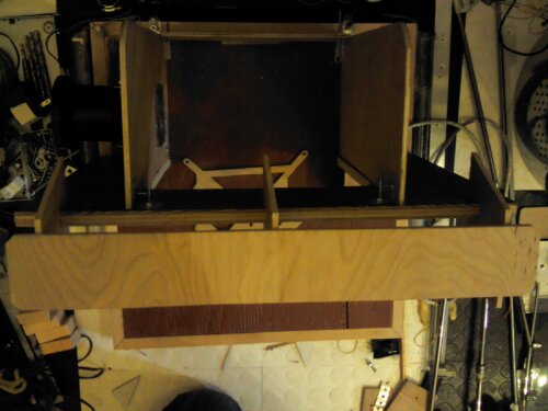
Above picture: This is a top down view of the above picture.
Update April 20th 2013—»
Today we got a little bit of time to work on Elsa. We mainly focused on mounting the main parts needed for the Z-axis. Both 10mm z-axis smooth rods are now mounted. Top and bottom as well as the motor mounts. The motor mounts share their substructures with the smooth rod mounts. Now all that needs to be done is to finish alignment and cut to length the 5/16ths threaded rod and finish the threaded rod top bearing support mounts. After that it will just be a matter of buttoning everything up, mount the motors and the majority of the Z-axis will be finished. I am still however trying to decide what size rods I want to use for X and Y axis. I can’t decide between 8mm and 10mm. I also got the round bezels for the z motor wire pass through that I will be cutting out as soon as I buy a new bigger drill bit. We are still throwing around ideas and drawing designs for the y-axis. As of now that’s where we are at with project Elsa i9.
Update April 28th 2013—»
The past week I have done most of the work due to outside commitments. I have found and mounted the final resting place for the Xbox power supply, as well as ran most of the related wiring. I have also started to build the custom spool mount and bowden setup. I have also buttoned down the Z-axis extensions and started the placement of the motor mounts. The motor mounts still need a little work before they are fastened down to their final positions. That way I can make sure everything is exactly level in all positions. I have been playing around with the idea of making the top of the z-rods adjustable for fine tuning later on. I just received my order of Abec 5 bearings from Italy. They were expensive but they work like a dream. I have never seen or used bearings of this caliber before and I am so impressed that I decided to replace all the bearings on every reprap I have with these. I also just started to design the power supply rail box that will be used to organize and split all needed power connections. This isn’t a requirement but I wanted it to be organized as well as looking in tip top shape for this build. Every aspect of this design will be thought out, built, used and then re-adjusted as needed. So nothing you see as of yet is set in stone. I have yet to update with new pictures but I will soon.
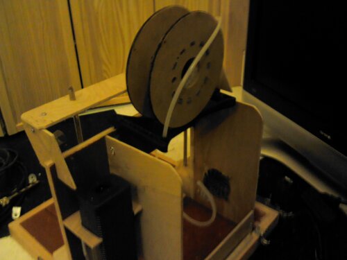
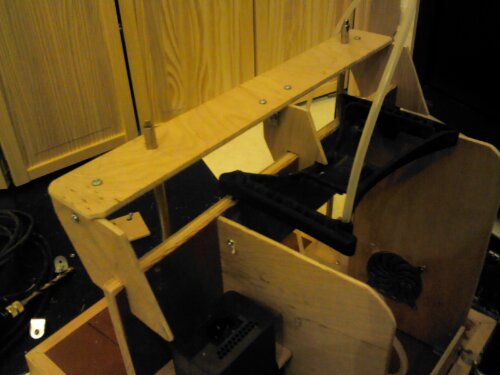
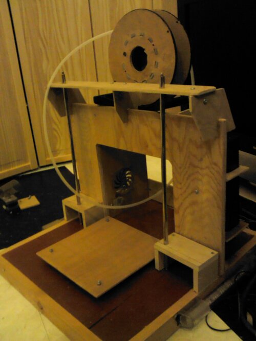
Updated pictures: Here’s the mock up for the spool mount as well as the start of the bowden setup.
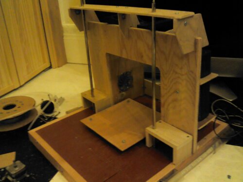
Here is some front views of the mock up to date:
Update: May 2nd 2013—»
I know its been a while since I last updated but I’ve been stretched pretty thin with all these other reprap related projects going on. I am currently designing the 3 different axis on Elsa. I’ve decided against lm8uu bearings in favor for a new custom Abec 5 608 bearing setup. I recently got some of these Abec 5 bearings from Italy. They are pretty expensive but they are definitely worth it. I have never seen any that can compare with the quality, this is the reason for the change from lm8uu bearings. I have started designing from the ground up for all 3 axis as well as custom bowden setup that uses LC variation of Wades design. I am really excited to start building the carriage and axis mounts. This will be an original design that I have never seen done before. A lot of these parts will be created using carbon fiber, aluminium and dibond in the final version. Each side of the lifts used on the z-axis will have 3 bearings each to move the x-axis and carriage up and down. As of yet the carriage will use 3-4 bearings and the y-axis will use 3-4 bearings as well. I have yet to decide whether the carriage and y-axis will require an adapted setup do to the fact that it is primarily regulated by weight. Early tests look good using adapted mounts that are restrictive in in wanted movements. Early mock up designs prove that this design has little or no known backlash. I will be updating as soon as designs are finalized and mock-ups are finished.
