JunkBot – Yesterdays Junk Is Tomorrow’s RepRap
After coming across the Adapto Thingiverse page I realized that the designers goals and the goals of my own are a lot alike. I’ve always had the urge to build a RepRap that can be built affordable as well as with lots of different materials. I am always seeing something in life that could be adapted into a printer. Adapto designer has already started the journey of building a RepRap that can be built with wood, aluminum and just about any other material that is within a reasonable size. I wanted to challenge myself to see if I could build my interpretation of the frame design with what I had laying around the junk pile. I also had to put my own twist on the design.
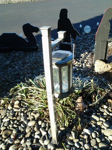
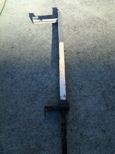
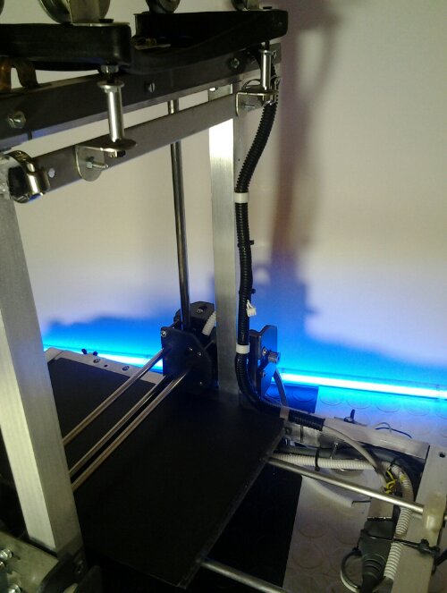
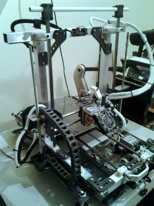
I found some square aluminum tubing that is about 25mm square. The aluminum tubing came off of some stands that hold up sets of outdoor solar lights. Each stand has a section that is about 14″ long with a junction that adds on about 4-5 more inches. The problem with the junctions is stability. They are plenty strong enough but the plastic inner pieces that make up the junction had warped over time. This was easily fixed by using old shelving brackets to hold the tubing in its correct form.
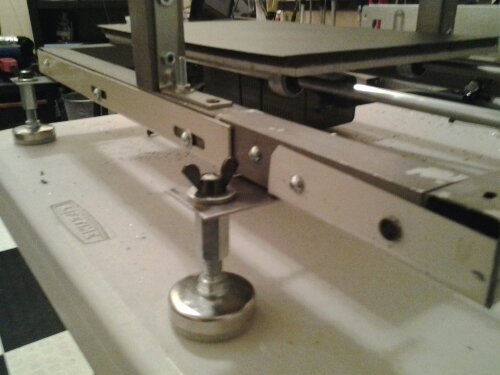
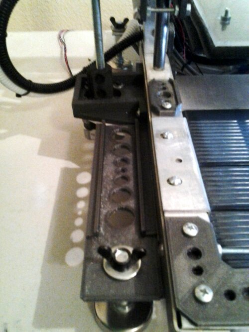
I also used metal shelving brackets to mount the vertical uprights. I could of easily printed the four feet used for overall stability but, I instead decided to use 4 L shaped shelving brackets with some scrap adjustable feet I had laying around. This gives builders an idea of other possibilities of parts that can be used. Because I used this bracket system for feet, I was able to space them out further from the frame which translates into better overall stability. The rods I will be using have been salvaged from regular old household printers. I was able to easily find them for free by posting ads as well as asking around. People are more than willing to let you take their old printer that has been sitting in their closet for the last few years or more. Another free place include E -cycle locations and you can always find them for cheep at thrift stores.
I was also able to find lots of usable wiring, endstop switches, rods, bearings and the occasional nema 17 stepper motors. I was able to find 3 stepper motors that would work perfectly for this build inside some old printers. I’ve found that the older and larger the printer, the better it was made. This means better parts as well as better odds that you will find usable steppers. After a little bit of stripping old household printers you will be able to look at a printer and quickly identify what rods it has as well as what kind of motor system it has. I will also be using belts that have been recycled from old printers. The belts actually are the exact same tooth, pitch and pattern of GT2s.
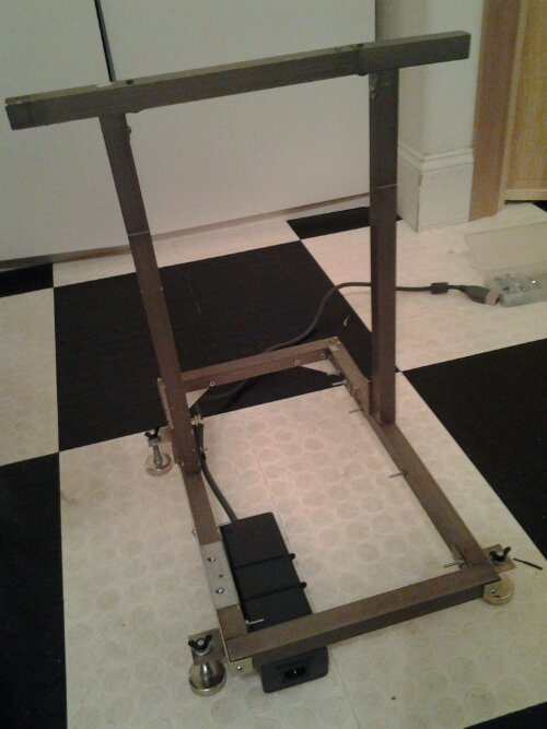
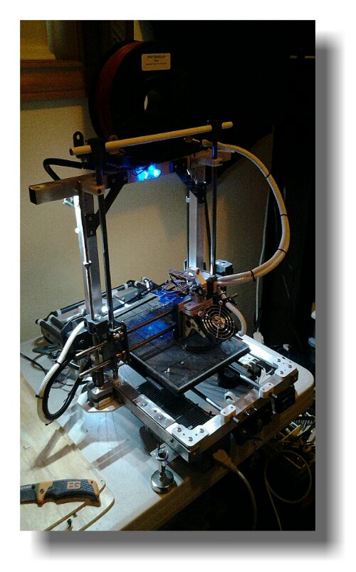
I’ve now got the frame completely finished and it is very strong. I now have to get to printing out parts to assemble the rest of the printer.
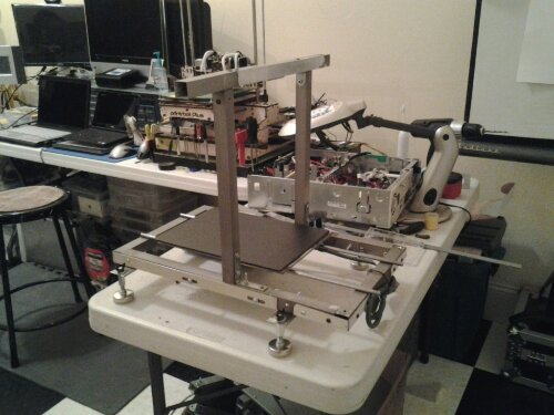
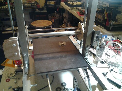
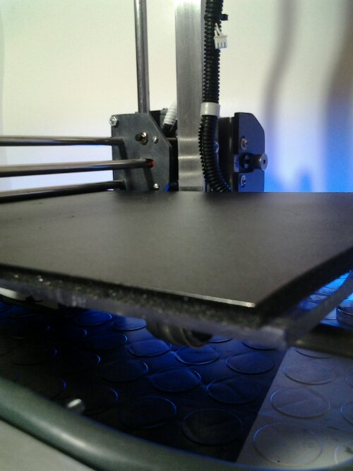
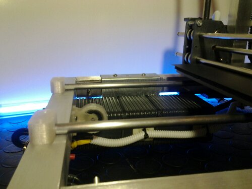
This is just a mock-up bed used to test fit everything. The final version will be a little bit larger.
After taking a few days to look at the design I decided to toy around with different linear setups. The thought behind this is the fact that I want to stray away from the standard lm8uu type linear bearing setup for something less specialized. If I can figure out an effective and accurate linear motion setup using parts that are common and easy to source, it would allow more people to build this printer. A few years back we had some very much experimental ways of creating a functional linear motion setup. Some better than others. I decided to dig through old designs and concepts to see if I could find one that fit within the requirements of this build. I found an old design that I built quite a long time ago just for proof of concept. It fits the criteria, so I plan on making a quick prototype for testing today.
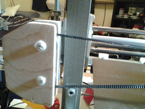
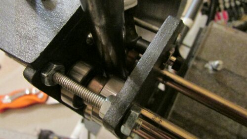
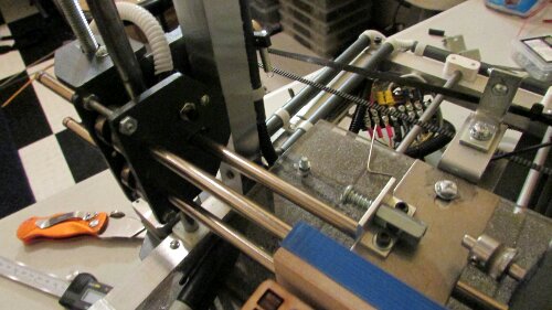
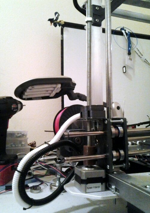
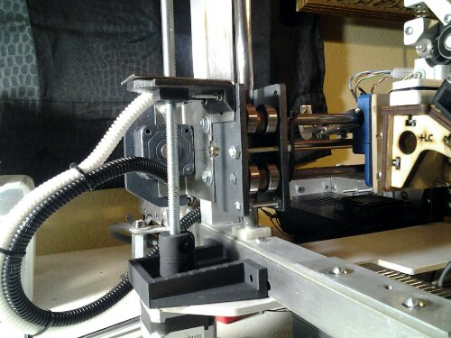
Quite a bit of progress has been made today on recycle bot. Recycle Bot is not the official name but merely a working name for easy reference. The z axis rods were put in place today along with the upper mounts and lower mount. I’ve decided to make my own model for the lower amounts as the ones I found on thingiverse were none too impressive. I’m using 11mm rods for the z axis but with this setup I have created, you can use any rods from 8mm to 14mm without any modifications to the z axis’s. I am played a third rod that interconnects with the z-axis, the third rod is also an auto tensioner system. I have yet to decide whether I will use this third rod for the x axis.
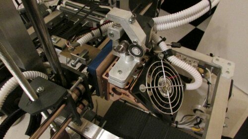
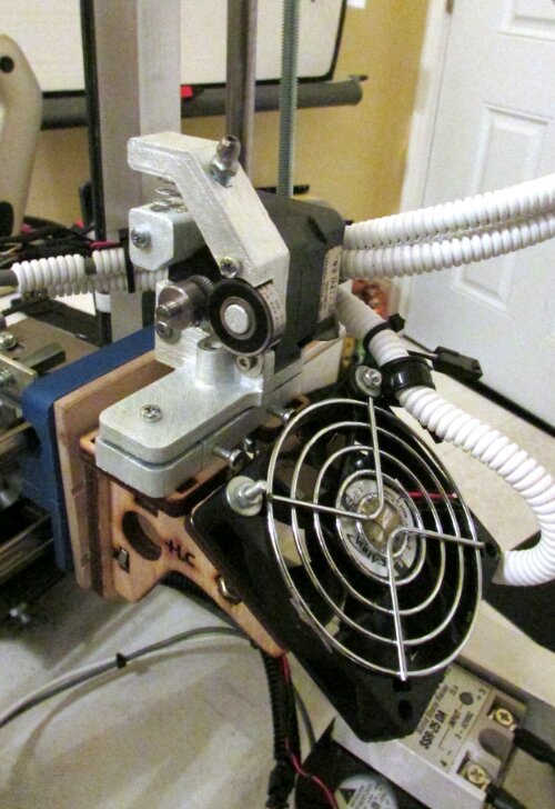
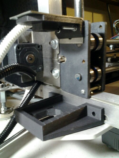
I have already built the carriage and I will be using a direct drive extruder from the designer of 3DPrintMi. You can find the extruder via thingiverse under 3DPrintMi and it uses the stock mounting holes as the v2 series of Printrbots extruder mounts. I am using the stock printrbot plus carriage from the v2 model, making a few modifications here and there. I designed the x axis rod spacing to be the same as the printrbot plus and LC. This makes for easy carriage modifications and adaptions. The x axis rods are 8mm in order the follow along with standard printrbot v2 setups.
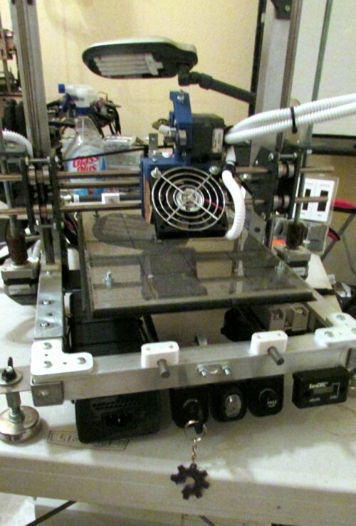
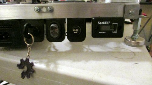
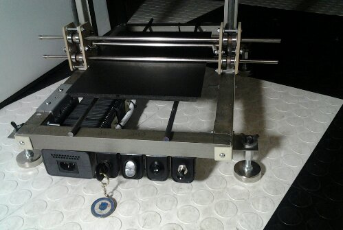
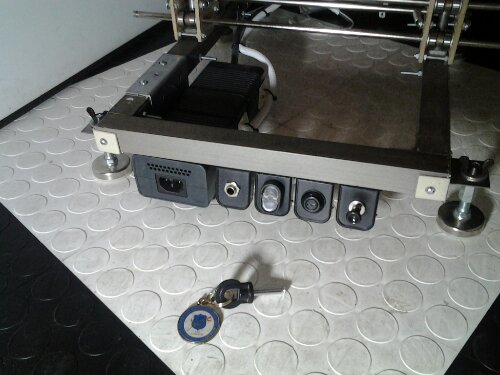
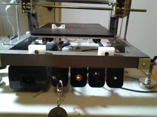
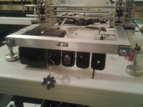
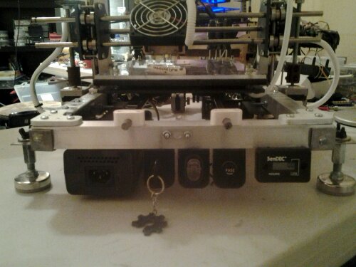
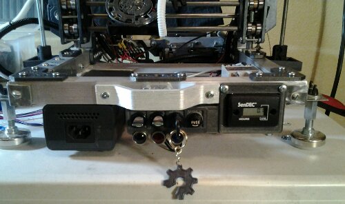
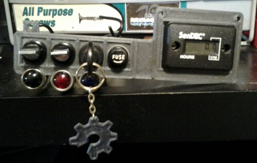
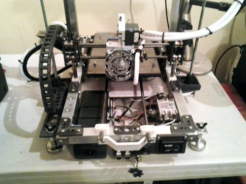
Today I was also able to make panel mounts for the fused lines for the power supply. I actually used a key setup that turns the Xbox PSU from standby to on. Yes, that’s right – I have a special key that is used to power my printer. I mounted another switch which is the main power to turn on and off the cooling system throughout the printer. This switch controls several fans that will be mounted to cool the controller and drivers. The 3rd switch is to turn on and off the task lighting attempting which will be mounted so the operators can see the prints as the filament is being layed down.
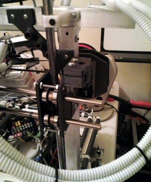
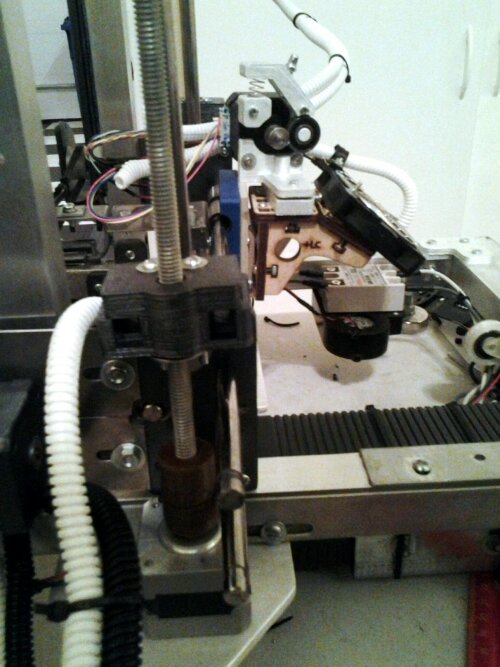
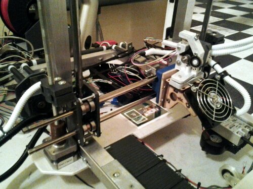
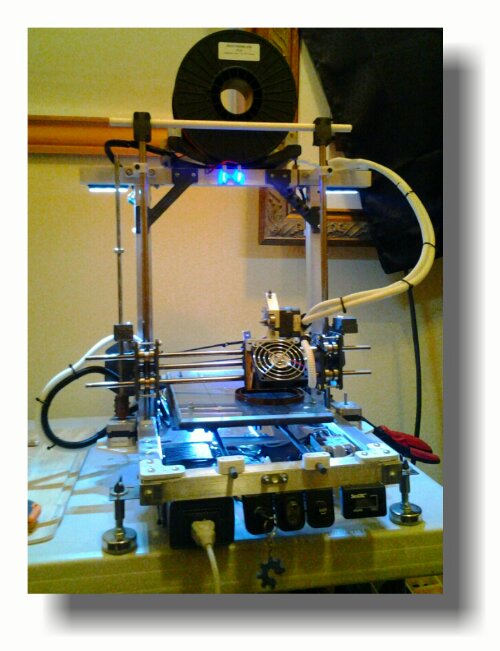
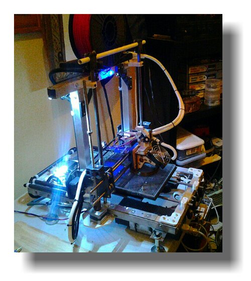
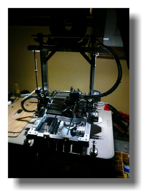
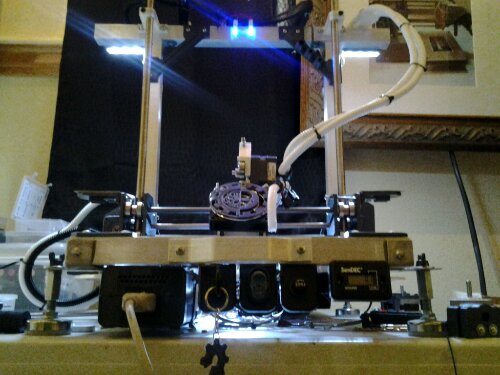
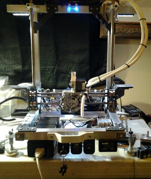
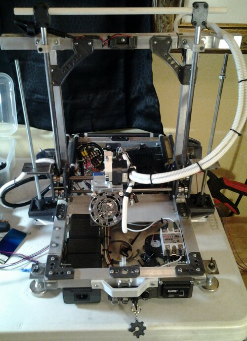
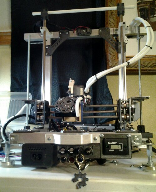
Here’s a few sneak peek pictures of the setup so far. If this is like any of my builds, lots will change over time.
Update: December 17th 2013
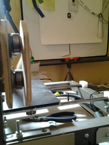
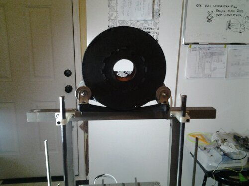
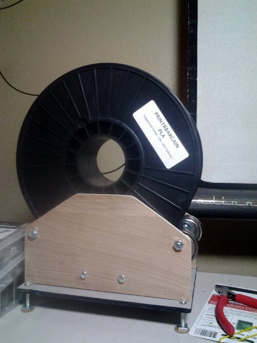
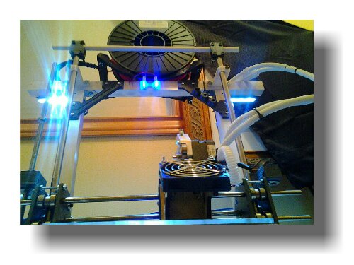
Today I was able to get a decent amount of work done. I’m almost finished with the top mounted adjustable spool mount. It has 4 – 608z bearings and can fit spools ranging from 63mm to 130mm which just about covers any spool I’ve ever seen. I still need to run the PTFE tubing but, I have yet to decide exactly how I plan on routing everything. I also figured out how I am going to mount the print plate using strong round magnets that will be imbedded inside of Lexan. I will also make a setup for an eventual heatdd bed. To start we will mostly be using PLA, nylon and a few other exotic filaments that don’t require a heated bed. I still need to figure out how I am going to do the setup for bed calibration as I am not happy with typical solutions.
Update: December 18th 2013
I was able to mostly finish up the x axis idlers as well as the x axis motor mount. I was lucky enough to find a stepper within an old household Epson printer with GT2 belts and a pulley. I still need to get a few more steppers and I have yet to figure out if all the salvaged ones work. I used 2 “L” shape brackets and did a little grinding to get the motor mounted the way I wanted. The x axis idlers are adjustable up to 4mm each and there are two of them. I used two because of the belt angle and I’ve found the a dual x idler setup works best for me.
I also printed out 4 y axis 8mm rod mounts. I decided to go with one’s from thingiverse under the title, “minamalistic MendelMax rod mount. ” I printed them with honeycomb infill pattern at 40%.and they came out nice and strong. They are a perfect fit with no cleanup needed after.
Update: December 19th 2013
Today I figured I would take the opportunity to print out some more parts. I decided to tackle the y axis idler as well as some experimental gt2 idlers. I’ve never used idlers with GT2 to three patterns on them. In theory they should offer up less ribbing within the prints. GT2 setups typically don’t have this issue so much because their tooth patterns are so close together and lower profile. It’s definitely worth trying out on this new build. I also printed out a idler set for the y axis, this is a combination mount and bearing sleeve. Both of these can be found on thingiverse.
I decided to also start printing parts for cable management as I believe now is the time to start figuring out wire routes. I still haven’t 100% figured out exactly where I plan on mounting the controller. I have it narrowed down to a couple different locations. I originally wanted to mount it under the carriage but, that left access to it a little lower than I would like. The most popular location would be next to the vertical extrusions but, that wouldn’t work with my z axis setup. More than likely I will mount the controller towards the back, somewhere on the horizontal pieces of aluminum. Mounting it there also allows for more airflow and a more simplified cooling system.
I printed off a couple of GT2 belt clamps for the y axis. I will mount those under the bed on both ends. I still need to decide how I want to mount the x axis belting to the carriage. I also found some 3 piece lm8uu bearing mounts that I plan to use on the x carriage as well as the bed. I have yet to decide on 3 or 4 bearing setups but, I am leaning towards 4. I’ve used 4 bearings on each axis on all my builds with great results. All of the printed parts on this printer so far are minimalistic. Meaning that they use just the required amount of filament to get the job done right. I did this to help keep costs down but, more importantly – print time.
Update: December 21st 2013
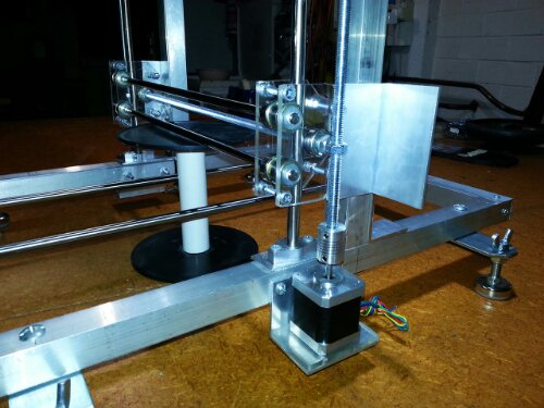
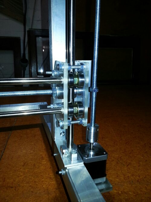
I decided it was time to strip down the frame and sand off all the old paint. I have yet to decide if I will leave it bare aluminum or paint it. I’ve always been a fan of black frames so who knows. I also mounted the GT2 idlers as well as the mock-ups for the motor mounts on the z axis. I debated back and fourth on if I would top mount the z motors or mount them down at the bottom. I tried both ways and it just seemed like mounting them on the bottom made more sense. The spacing between the z axis rods is 30mm which is about the same as most Mendel’s. I still need to do all the final sanding and figure out if I’m going to paint or polish. I should be able to update tomorrow with pics so you can see the progress.
Update: December 22nd 2013
I took the entire printer apart in order to sand off all the old cracking paint. I originally wanted to paint the frame and I still might but, it is a lot of preparing and use of etching chemicals that are not cheap. For now I’m debating leaving it with a brushed aluminum look. In order to brush the aluminum you have to make a little jig that allows you to use sandpaper to sand lines in straight lines. I used 150 grit sandpaper to give it that look which turned out pretty nice. More then likely when I’m finished with all the parts I will either clear coat it or use a special waterproof paste that I make which will seal the aluminum as well as make it more durable. I used an electric sander to get off the bulk of the old paint and then hand sanded the fine details. I just finished putting the majority of it back together.
Update: December 23rd 2013
Made a lot of progress even though it doesn’t exactly look like it. I did a decent amount of wiring and also installed a second set of led task lights that are going to be used to light the hot and cold end for cleaning as well as filament changes. I’ve noticed on my printrbot plus that I can never see very well when working on my extruder, so this will help a lot. I dismounted all the wood pieces and treated as well as clear coated them all. This will help eliminate any swelling due to temp or humidity changes.
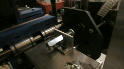
I also was able to wire up the x axis endstop or homing switch using a simple push button style switch. It is the exact same switch that is used on the Enventorbot. I’ve noticed too much play in the activation of lever actuated switches. The only downfall of using this type is the lack of the clicking noise associated with the lever mechanical switch. That can easily be overcome using a multimeter on the endstops, doing this gives you a voltage change when activated.
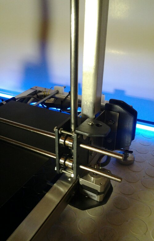
It took a a few minutes to take the setup apart. That’s another nice part about this integrated setup, it is very easy to take apart. I also finished up the z axis motor mounts on both sides but, I still need to physically mount the motors. I’ve also decided to add an adjustment for the z motor mounts which will make getting everything just right, a lot easier. I should be getting in some more filament within the next few days or so. That way I can start to print the rest of the printed parts.
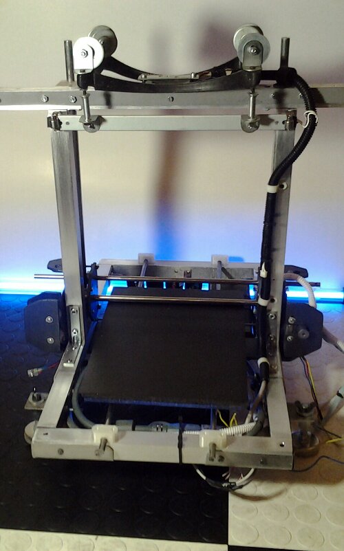
Update: December 25th 2013
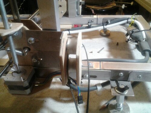
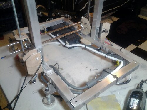
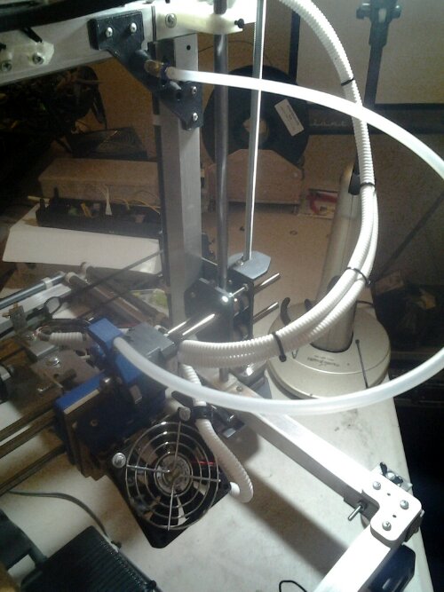
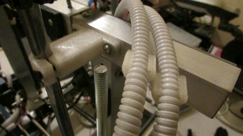
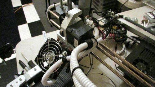
A good deal of work has been done. I’ve started to pre-wire a lot of the bot as well as setup the majority of the cable management. The rear 3 aluminum frame pieces have conduit mounted neatly on them to run the majority of the wiring that needs to be above the frame. This helps to eliminate any chance of snags or accidentally bumping cables. I ran the extruder wiring up the right rear vertical bars and up over the top. They have swivel mounts on the top of the frame that hold these two sets of cabling. The main purpose for this mount is to allow all the wiring that is going to the extruder to move back and fourth automatically to mimic the carriages movement. They also hold a very soft bend which helps to save your cables from fraying inside.
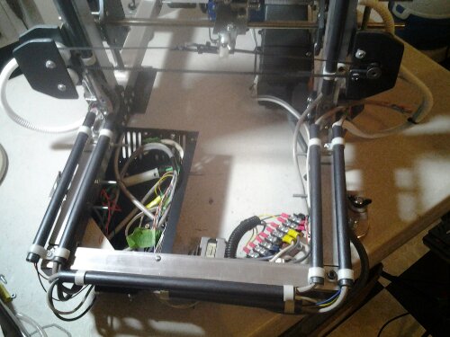
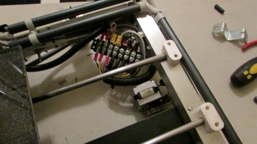
I also decided to hack off the Xbox PSU end piece because the cable was way too long for the platform. I used an 8 pole terminal block to split out all the power supplies wiring which will ensure good connections as well as save a lot of time down the road. The terminal block is mounted at an angle with a hinge so that it can be easily manipulated if needed. I will also try and update with new pics of the new add ons.
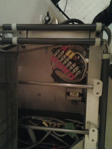
Update: December 26th 2013
I finally figured out how I plan on mounting the carriage to the x axis. I have already mounted the ubis DDE from 3dprintmi and it can be found on thingiverse. I decided to go with 3 lm8uu bearings for the x axis but, eventually I will more than likely change it over to run on standard 608 bearings to help keep down specialized part counts. I will use this printer to make the 608 bearing mounts. I took a page from printrbots book and made a small square adapter plate to mount the rear mounting plate. The main rear mounting plate will hold on the lm8uu bearings.
Update: December 28th 2013
The carriage was finally mounted on the x axis and to my amazement it slide on the rods better than my printrbot plus. It’s always rewarding when you design two entirely separate pieces and then they fit together perfectly. The y axis bearing mounts were put together and mounted on the beds sub mount as well. Since the belts for the x axis Sat back behind the vertical bars and bit I had to also make an extension for the GT2 belt clamp. I decided to go with a 60mm fan for the extruder as I’ve found that the 40mm fan doesn’t quite cut it. Almost all the wiring has been plumbed throughout the bot. I built a sub mount which will hold the electronics on the rear right portion of the printer.
I’ve found that Ethernet cabling can be found for very cheap and re-used for a good majority of the wiring for a printer. The thermistors and endstops can use single strands of the Ethernets twisted wiring. While the motors require you to twist together pairs of wiring to make thicker connections for each line. Doing this insures that you are not using too thin of wiring. The down side is that you must buy the molex connectors and crimpers unless you want to patch the wiring to the plugs you already have. I prefer the cleaner approach and I will post details once I order the parts.
This afternoon I started to print some of the parts I’ve been planning on printing for a little while now. One of them is the dual led mount that holds 3 less on each side. This should help to keep everything lit up during operation as I’ve found this to be important. I also started to print the top vertex’s for the left and right side. These will help reduce any side to side sway which is very important for this design. Acceleration and deceleration on the x axis can cause some inconsistencys if your vertical beams are not rock solid. These will help to insure that this is so. I will more than likely run my printer most of the day and hopefully I will have time to update with pictures that I haven’t done in a bit.
I’m also in the midst of figuring out a fan setup that is specifically designed for tall prints and bridging. I’ve found that using a fan in specific ways for these types of prints can be very important to getting quality prints. I plan on mounting an 80mm fan specifically for this with its own fan controller that I can adjust on the fly. I still need to find an adjustable mount as well as figure out a possible track system for the fan. This will give me the most amount of options and coverage.
Update: January 1st 2014
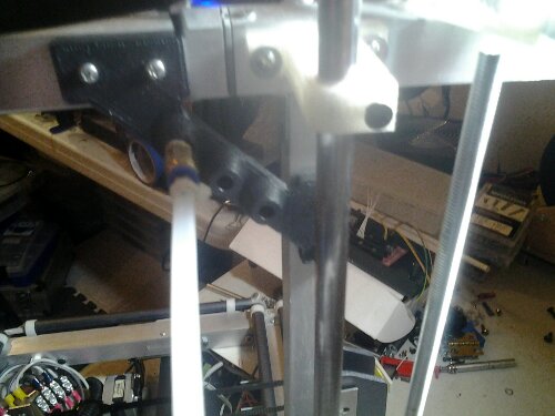
Today I plan to take care of the smaller parts needed like belt clamps etc. I will have to use a friends printer as mine is currently down. Yesterday I printed out a spare upper vertex with mounts for a bowden feed tube. I threaded a push fit connector onto it to make dismantles quicker. I so modified the intake on the DDE to accept a fitting for the extruder side of the tube. Even though I’m not using a typical bowden setup, I’ve found that using a PTFE tube between the spool and the extruder keeps everything from tangling during operation. I also wired up the thermistor and power torn the extruder. I plan on wiring up a portion of the motors on the controller end as well. I will have to order a little bit more wiring before I’m completely finished.
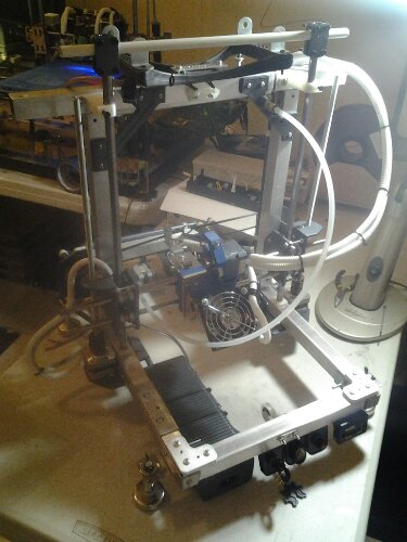
Update: January 2nd 2014
I spent a good majority of time to make sure that the brackets I made for the inner vertical rods were mounted correctly as alignment is important. Adding the T brackets to each side, more than doubled the rigidity of the frame. I now believe that you could easily stand on top of the printer without any signs of flex or stress. I can thank the carefully planned combination of metal and printed brackets. The inner upright brackets have 6 bolts each and are very strong. I also added a 20 amp fuse between the board and the power source just to be safe.
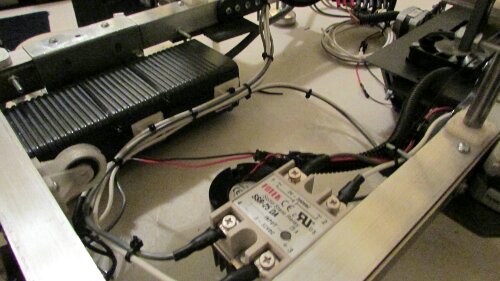
I haven’t decided for sure if I will run a heated bed on this printer 5 if I choose to I will also run a fuse between the power and the heated bed. The heated bed of course will be wired using a solid state relay as I believe that is the best way to go offering up extra protection to your control bord. I also have a set of newly printed parts to install including: 12 millimeter z axis top stabilizer rod and a few other smaller pieces. I mounted to 50 millimeter fans, one on each side of the boards case to give some active cooling that will be controlled via switch
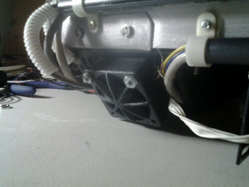
Update: January 3rd 2014
Lately I’ve been doing lots of updates on my progress but, not much in the way of pictures detailing that progress. So this update will be primarily pictures showing those updates. I apologize in advance for the quality of these pics as I am attempting to get something with better quality.
Update: January 4th 2014
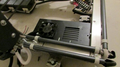
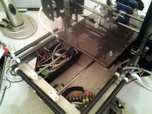
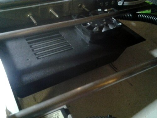
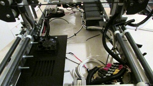
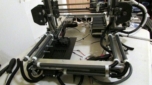
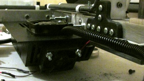
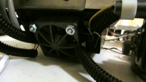
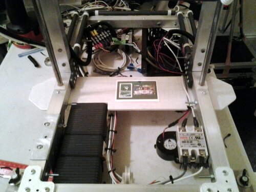
I finally figured out a cover for the controller bay. It has two sets of vents on it and on one of them I mounted a 60mm fan to expel any heat that rises to the top. This will work great in conjunction with the other two intake fans. So cool air is brought in both sides via 50mm fans and the warmer air will naturally rise and be pulled up and out by the top mounted 60mm fan. If those isn’t enough than I still have space to mount another 60mm fan on the top. Each of the individual motor driver chips will have heatsinks as well as each mosfet. The controller should be more than happy with this setup. Another good reason for the the top cover is to protect the controller from any foreign debris that could potentially short out the board if it were to fall causing improper contact. The top vents on the cover have a piece under them that will stop anything from falling on the board while allowing air to pass through.
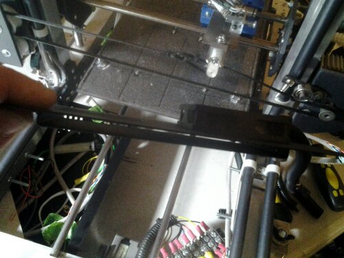
I still need to figure out how I plan on mounting another 60-80mm fan that will be used for tall prints. I need something that is adjustable in order to get the best angle depending on what I’m printing at the time. I also changed up my z axis homing switch with a printable solution. I found one on thingiverse that was originally intended for a printrbot plus or lc. It fits perfectly wiithin it’s intended location. Typically the z axis switch is mental to be mounted on the x axis motor side. The reasoning behind this is because the motor side typically weighs more causing that side to sage a bit. With the integrated X and Z axis, that is no longer an issue. So it just made more sense to mount it on the right non x axis motor side. I’ve also been messing around with different materials for my auto-tensioners for the X axis. I originally had it setup to run 4 high tension springs with one on each side of the mount. I’ve tested rubber bands as well as thicker belting and in some circumstances they work better. So I will need to test out different methods to see which is the best fit.
Update: January 5th 2014
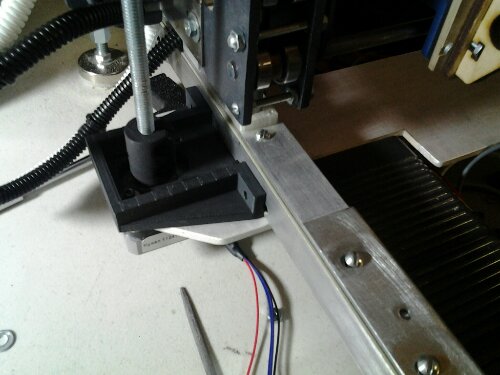
I printed out some bearing holders for the top of the z axis as well as some stabilizers for the z axis nut traps. The bearing holders were found on Thinigiverse and originally designed for the Ord Hadron. They stabilize the z axis rods at the top which is a design I’ve been wanting to mess around with. I haven’t decided if they will be kept as a part of the final design yet. The z nut traps are quite brilliant in design. I will have to make a few altercations to the z axis nut trap setup in order to install but, I’m sure it will be worth the effort. They are comprised of two pieces to each side which lock together with channels as well bolts. These two pieces encase the z axis nut and then bolt onto the x bridge.
I started putting together a parts list but somehow my tablet are it for lunch so I will have to rewrite a new one. Tomorrow I plan on printing out a 60mm fan cover for the fan mounted on the top of the controller bay. I also need to finish a bit more wiring before moving forward with actually drilling the holes to mount the y axis rods. I also ordered some locking waterproof connectors to test out on this build. I was able to get 40 of them for $2.50 with shipping included. I also want to order up some ferrus connectors for the screw terminals on the controller. RepRap magazine recently released an article on the issues of not using these connectors on boards with screw terminals. You can order a hundred of them on eBay for a few bucks, so one order would last me a lifetime. I just need to double check the gauge requirements.
Update: January 7th 2014
I’m still awaiting the arrival of a solid state relay so that I can run a 24v silicone heated bed. I will be running a massive transformer just for the heated bed. It will output in 24 volts AC but that doesn’t matter as far as the heated bed goes. I will also run an inline 15-20amp fuse before and after the transformer in case any issues arise as it will cut the power. I haven’t completely decided on how I plan on mounting the bed and aluminum plate. I will probably not use springs as they have been known to be an issue.
The 24v heated bed running AC should in theory heat quicker then a standard 12v DC heated bed. Silicone beds have also been known to heat quicker. It will probably be another week or so before I get the SSR (solid state relay) needed to completely wire the bed. I am also still waiting on a loaner ramps board that will be used for this bot as the only one I have is for mock-ups.
JunkBot’s Parts list:
JunkBot was originally created to show people that with some creativity and ingenuity – a great printer can be built. We give a general parts list below, as well as some ideas of other usable materials. This way you can start putting together a collection of parts to make your own JunkBot
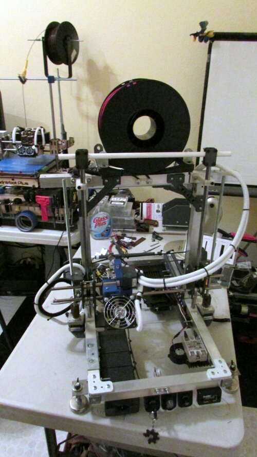
Main Framing Material: I used stands that were originally created to hold up outdoor solar lights. They measured 1″ by 1″ or 25mm by 25mm and they are made from aluminium. Almost any material can be used, including wood, extruded aluminium or steel.
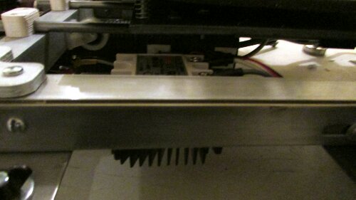
(10+) 608 bearings: 8 of them are used on the z-axis. There are also 2 others used for idlers within the x and y axis’s. These bearings can be found within roller-skates, roller blades and skate boards. You can also buy them online from many different sources but, the cheapest option is to recycle them from old roller blades found at thrift stores or garage sales.
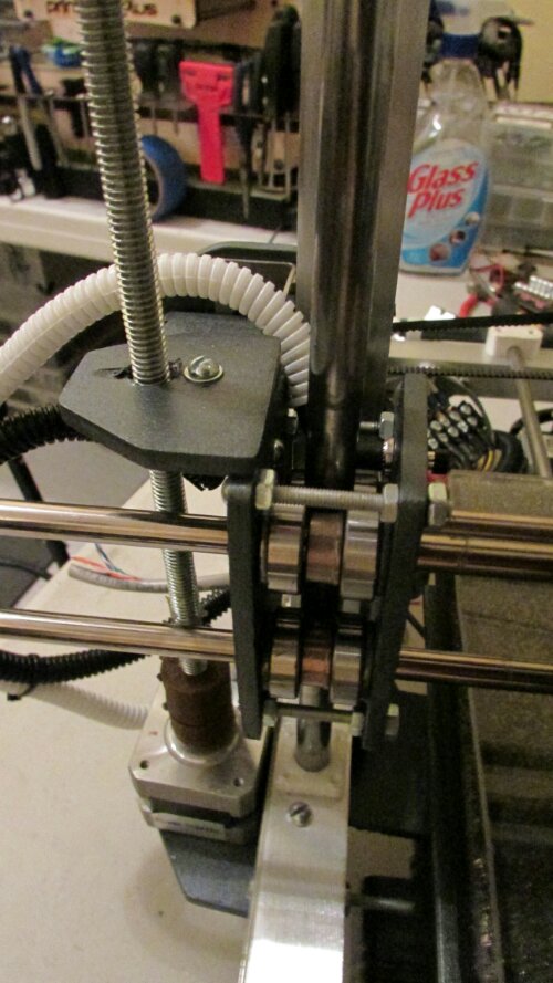
(8) LM8UU Linear Bearings: 4 for the x axis and 4 for the y axis. A later iteration is planned to be done to help eliminate the need for these more specialized bearings. You can find them online for about $1 or so a piece depending on quality.
(2) 5/16ths threaded rods or 8mm. Other sizes can be used but the specialized z nut setup is designed to use this size rod. You can always use smaller rod if you would like to change the z nut setup.
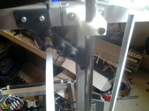
(4-5) 8mm or 5/16ths smooth rods for the x and y axis’s: We also added an extra rod to the x axis for the auto tensioner system but, you can use regular 5/16ths bolts if needed. We usually find our 8mm rod within old household printers and scanners. Your local E-Cycle location will usually give you a few for free. you can also look on sites like craigslist for broken ones that people are usually excited to give them to you.
(2) Smooth rods in any size from 10mm to 16mm: These will be used for the z axis. the reason we give a range of rod sizes is due to an auto-tensioner system that we developed that allows you to use different size rods without any modifications. (We are using 11mm rod for our z-axis because its what we had available.)
Zip Ties: These little guys come in all sizes and I use them often. They work great for keeping cables together as well as many other uses. I primarily use the small ones but, you can find assorted packs with several sizes for a few bucks.
An Assortment of washers, springs, nuts and bolts:We have not counted every nut and bolt and we probably wont post a list of them because the JunkBot is all about hacking everyday items apart to make a nice 3D printer. We used whatever we had laying around and did whatever it took to get the parts we had – work together.
Assorted Brackets: We used a few metal brackets to reinforce the frame. We also used some printable brackets to make it very strong. You can use one or the other to build JunkBot. If you look at the pictures you will see the important locations to reinforce.
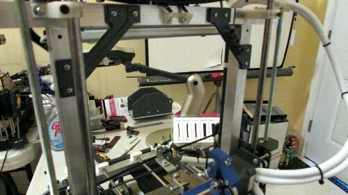
Some Sort Of Feet: These can be printed or metal adjustable ones can be recycled or bought. We recycled a set off of an old stand and used some L brackets to mount them to the frame. You can find printable ones on thingiverse.com under the (Adapto Build)
Wiring: We used primarily CAT5 wiring or ethernet cables. These are cheap and efficient. To wire each motor use 1 CAT5 cable. There are 8 single strands of cabling within each cable. You will want to double these up to wire: Motors, Extruder Power and Heated Bed Power. You can use individual strands for endstop or homing switches, thermistors, low amp fans and low amp LEDS.
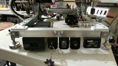
Switches, Fuse Holders and LEDs: Not required but, I use a switch to turn ON/OFF auxiliary cooling as well as to take the xbox Psu off of standby. Its also nice to have a few status LEDs wired to let you know things like: is your hotend on or is your PSU on standby. We run a 18-20 amp fuse before and after our power supplies as well as with a solid state relay on our heated bed. The Xbox PSU has built in power management so no need to worry if you dont have any fuses as they are not required.
Flexable Conduit Tubing: This is used to protect wiring as well as organize it. It is by no means a requirement but, its very cheap and it is very useful. You can buy about 14+ft for about $2-3.
Hard Wiring Conduit: This stuff is what is used on the back of JunkBot to hold the wiring along horizontal frame sections. It is also not required. It can be found in the audio/video wire management section.
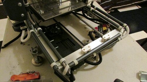
The Top Spool Coaster: Ours is actually made from a handle off of an old large fountain Pump. It actually ended up fitting perfectly and is adjustable to accommodate any size spool. There are hundreds of downloadable spool mounts that can be found on thingiverse.com

Fans: The amount and size of fans needed is entirely up to you. Typically you will want at least one to cool PLA near the extruder as well as some to keep your electronics nice and cool. For this build we are using 2-50mm intake fans to cool our electronics with a 60mm top mounted exhaust fan. We also mounted another 60mm fan on our extruder to cool prints as they are laid down.
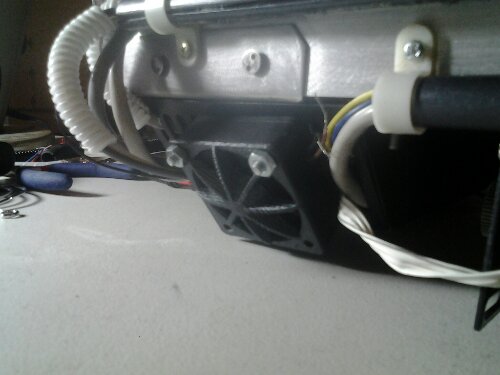
Heat Shrink, Connectors, Electrical Tape and Misc: Heat Shrink tape is a great way to securely patch together wiring. We used a decent amount of it to keep splices protected so that they dont later come unplugged. Assorted connectors are something that every builder should have. We use them for all kinds of RepRap related projects but specifically for this build we used them to attach wiring to out terminal block. All of these items can be found online or at your local hardware store.
Xbox 360 Power Supply: The version we are using is the 203watt 16.5 amp OEM Microsoft version. We have heard of other users having bad luck with cheap knock-offs and we recommend getting the real deal. (We also have a complete write up on the site that details the types and modding of an Xbox PSU to use with your RepRap.
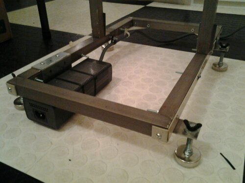
Controller Bay: We used two separate pieces from a metal DJ light case that we found in my buddies garage. Be creative and if creativity isn’t your strong suit then jump on thingiverse for custom options that will work with just about any controller you decide to use.
EndStop or Homing Switches: You will need 3 of these for this build. You can find these in all sorts of different electronic items. We decided to buy a new set of non-lever actuated switches to test out for this build. just about any momentary switch can be used if wired correctly.
8-Way Terminal Block: Ours was taken off of an old project we had laying around but, if you dont have one you can find them online for a few bucks. This is not required for the but, it helps to simplify wiring.
Hotend: We used a Ubis hotend from Printrbot. This is one thing that people generally skimp on and later regret it. Buy a quality hotend and you will be happy you did.
(5) Nema 17 Stepper Motors: We were able to salvage most of our steppers from old office printers. You can find them online from about $5-15 each. I personally prefer Kysan motors but, they are on the higher side. Make sure you do your research before buying and just because some guy online says that they are for 3D printers doesn’t mean that they are.
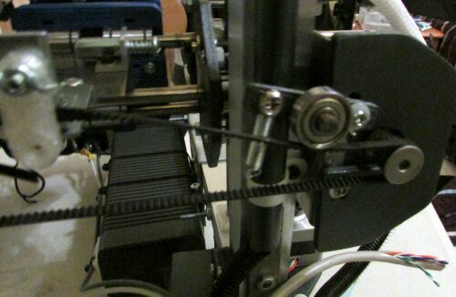
Belts and Pulleys: We always recommend buying GT2 6mm belts and aluminium matching pulleys. You can find them for a decent price and get enough to do the whole bot. For about $20 you should be able to find 2-3 meters of 6mm wide 2m pitch GT2 belts and aluminium pulleys.
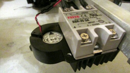
Solid State Relay (SSR): This isn’t required as you can run the heated bed directly from the RAMPS board but, I have a 24volt heated bed laying around so I might as well use it. I will also be using a 24 volt transformer to run the heated bed.
Controller: We will be using a RAMPS 1.4 kit solely because of cost and the fact that it is widely used. The Ramps board has a huge support community which is good, especially if your new to these types of setups. I commonly see Ramps kits including: Arduino Mega, Ramps 1.4, 5-driver boards, heatsinks, wiring and SD card kits for anywhere between $35 and on up from there. If you watch eBay auctions closely, you should be able to snag a kit for around $40-50 without too much of an issue.
Update: January 15th 2014
I will be adding a section to the BOM that will link to every part printed from Thingiverse but, it will take a little time. In the meantime if you can’t find one of them for your bot weather it’s a JunkBot or not, let me know and I will get you the link asap. Today I wired up the switch to the main cooling fans for the electronics bay as well as the inline 20 amp fuse. I also cleaned up and organized wiring from prior work. I just finished the wiring for today and I will add pictures as soon as I can. Some more parts should arrive tomorrow and hopefully the ramps wiring kit is in that shipment of stuff so that I can finish the wiring on the controller end. This will allow me to at least flash the firmware and test out the motors. I am still in need of about 3 meters of GT2 belting as the ones I have seem to be a bit to short.
I took a few more pictures to show better details.
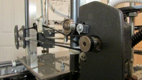
The JunkBot is looking better than ever with the new updates:
Update: January 17th 2014
Today I was finally able to put together the new z axis nut traps. These were designed using a lot of thought and engineering. It uses two pieces that lock together with a channel as well as bolts for extra strength. The two pieces enclose the z axis nut with a spring that loads the nut to keep tension. I have yet to decide if I will make anymore modifications to the z axis nut traps. I might beef up the metal mounts by changing them out with steel ones but, so far I’m happy with the ones that are currently being used.
Update: January 19th 2014
Yesterday and today quite a bit of work has been done on the JunkBot. I rebuilt the z axis motor mounts by connecting them with one solid piece instead of two pieces. This also serves as a cross brace for the base of the frame. It also helps to keep wiring nice and neat as well as keeping it out of the way of the y axis linear system. Yesterday I finished wiring everything on the controllers side and also finished all the wiring for the active cooling setup for the electronics + Solid state relay. There are 4 fans in this cooling system and eventually 1-2 more that will be dedicated for printing. The 2 for cooling prints will be controlled by the ramps controller in order to change speed through Repetier.
Update: January 28th 2014
I’ve been real busy with all the different projects going on as well as the dual extruder upgrades on my printrbot plus. I finally have some time to tie up a few loose ends with the JunkBot. A big issue I have with my Plus v2 is task lighting. Being able to see your prints is more important than you might think. I do a lot of adjustment on the fly AKA while printing. With the JunkBot, I didn’t want this to be an issue so I added lots of task lights. The more recent additions include bright leds in sets of 3. I mounted one on each tower to illuminate the entire bot as well as another under the bot to light up so I can see well during adjustments and troubleshooting. These 3 are set on rotating mounts, so I can adjust their spots up to 180 degrees. I mounted as well as finished all the wiring for these lights.
Update: February 3rd 2014
I have been working on the z axis setup again even though I previously finished it. I wasn’t completely satisfied with adapting available designs to fit my requirements, so I will be custom designing a few parts. I also replaced the z axis’s motor mounts with adjustable ones from the adapto RepRap. I also plan to clean up a little bit of the wiring as I’ve found water proof connectors that lock in place. I’m still debating on using a few status lights as I recently bought 3 of them and they are about 7 mm in diameter. Just was able to get the panel mount status lights in red, green and blue. I figured I could use green for power, red for heating and blue for wether or not the cooling system is active. I plan to add a more detailed update once I finish the designs and print the few required custom pieces.
Update: February 5th 2014
In the last few days lots of work has been done on the JunkBot. I could have more than likely had it finished already but, I want it to be the best it can be when I fire it up for the first time. I’ve made a few simple parts on Sketchup, exported them as STLs so I could easily print them on my printrbot plus. The first set of parts are for the z axis nut retainers. I decided to reinforce them with steel L brackets. I finally decided to go with the z axis motor mounts from the adapto build as the are adjustable as well as very sturdy. Both motor mounts are also reinforced with 6mm birch with cutouts for the motors.
I managed to find an awesome half skull, half cyborg skull surrounded by gears on thingiverse. After a little re-scaling and a lot of on the fly print adjustments, I was able to get it to print flawlessly on my plus. It is a very detailed print with no room for error and it turned out great. I used this piece as a fan grill for the JunkBot as I feel that it fits right in with the personality of the machine.
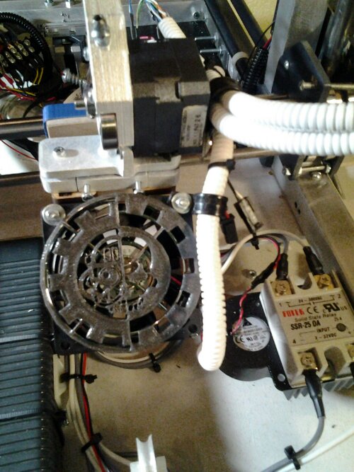
I replaced my 2 90 degree corner brackets with one’s of my own design. I just wanted to create something simple that had more personality than the plain ones I originally had on there. I might throw them on thingiverse.com if I have some time but, I will definitely put it up when I finish the JunkBot so others can build their own kind of JunkBot.
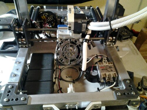
Update: February 9th 2014
Lots and lots of work has been recently done on the JunkBot platform. I’ve replaced a good portion of parts that I wasn’t a 100% satisfied with. I’ve been designing and printing parts over the last week. I now have a few pictures to show. The z axis is finally completed and is in great working order. Today I have spent a lot of time designing a new top mounted spool holder that not only fits well on the frame but, it also follows the design queues of the JunkBot. I also redesigned the front panel as well as added some status lights.
I managed to find 2 matching aluminum switches that manage active electronics cooling and the majority of the task lightning. As you can see in the pics below, I also designed replacements for the upper vertex’s. I wanted something strong as well as something with my own tastes involved. The task light mounted in the center on the top also needed some re-inventing. The leds used have square mounts on them. I made nice little boxes that they fit well inside.
Update: February 15th 2014
I’m planning on doing a little bit of rewiring on the JunkBot today because I’ve changed the front switch panel so much. I have also discovered these great little connectors from my local army surplus store that are water proof. These connectors are easily removed or changed but, they also do a great job of holding together multiple slices at a time. I have also started a few different carriage designs so that other builders can print the exact same setup if they choose to. It has taken quite a while to build something that is easily adaptable for various setups.
I hope to have some time to start digging into firmware setups as well today. I haven’t decided a 100% on one firmware over another but, more than likely I will use Marlin or a variation of it. It’s easier to use or adapt an already fully working setup than to start from scratch. The active cooling setup for the electronics is also on the list of things to wire today. Hopefully soon I will have some updated pictures of the current progress being done.
February 25th 2014
Lots of updates including a new cable management setup. I wanted to post a few pictures of whats been done since I haven’t had time to update the build log.
February 26th 2014
The lower piece in the picture that is under the drag cable is what I call, “the track.” It is a piece that I designed for the drag cable to rest in when its at its lowest position. The track isnt required but, I found that it helps to keep the cable going the right direction at all times. Without the track it sometimes can startnto move at a slight angle which could cause some of the links to stick. It takes about 50 minutes to print 8 links which isnt very long at all.
A decent amount of cleanup is needed after printing the links. This is needed in order to make each link rotate smoothly. I used a small needle file and a razor to cleanup any of the parts that move. The links that make up the cable can be found on thingiverse. I made a few slight modifications to the thingiverse files but, they will work as posted.
Once im finished I will post links to any designs I used as well as post any custom designs I’ve made on thingiverse. I am currently organizing all the JunkBot files as well as re-labeling file names. I will also make sure to post which files are required and which parts are optional.
February 28th 2014
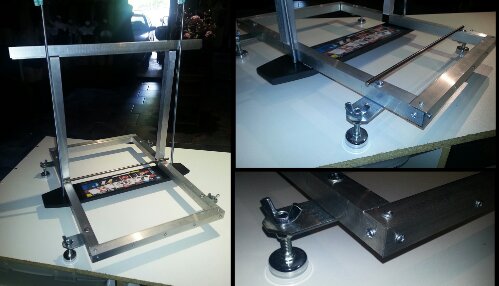
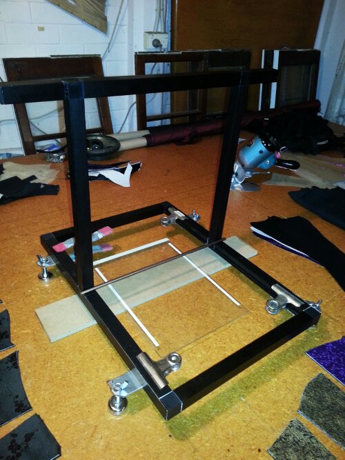
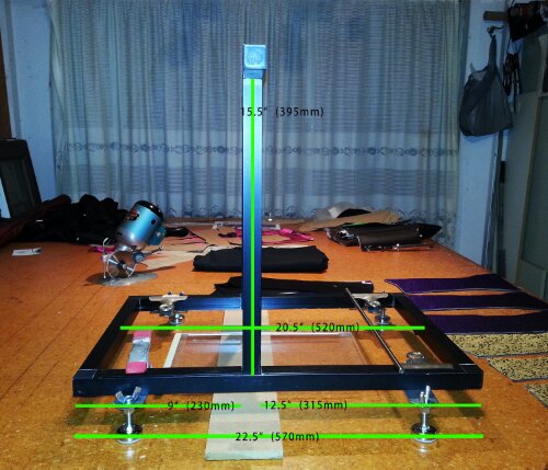
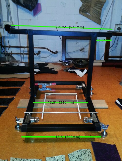
I thought it would be neat to show you guys the 2nd JunkBot being built in Australia. This build isnt yet finished but its almost there. The 2nd JunkBot is being built using 25mm aluminum tubing recycled from stands that are used to build store displays. I have recently been organizing all the files used to create the JunkBot and we hope to have those files available soon. One of our main computers went down which has delayed the process a bit. Here’s a few pics sent to me from our fellow JunkBot builder.
The dimensions posted in the pictures are different from our JunkBot but, thats one of the nice parts about this platform. You can adapt the frame to fit your needs or what parts you have available. I really like the JunkBot logo he added in the cross support. Its really starting to come together!
Update: March 30th 2014
Here are some new updated pics that I just received on the 2nd JunkBot being built in Australia. It is coming along nicely and looks great.
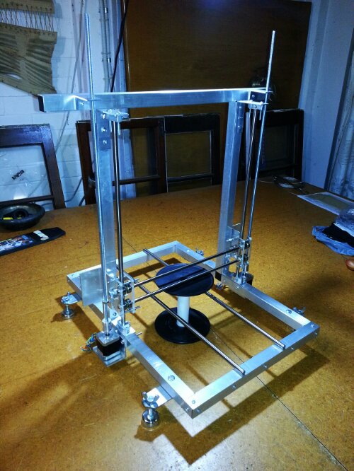
Update: March 27th 2014
I haven’t been able to finish the JunkBot but, I am very close. I plan to test out each axis’s motors soon as well as the rest of the electronics. I also need to deturmine which software im going to use. I have been spending a lot of time organizing all the design files that were used to build the JunkBot which is very time consuming. I also want to redesign the carriage to make it a easily buildable or printable design. More than likely I will use ABS plastic for this portion as well as a few other parts that require the use of ABS plastic.
I was recently able to refit my main printer with a new heated bed and auto relay setup so that I can print these remaining parts. I also need to finish the drag cable system. I recently perfected the design which will match the one used on the Printrbot Plus hybrid that we have. Now that the drag cable system has been tested with quite a few printing hours under its belt. I will also try and finish organizing the cabling that is going into the electronics bay as I work to finalize the wiring required.
Posted from RepRap Squad HQ
Posted on December 4, 2013, in RepRap Squad's Projects and tagged 3D printer, adapto, cheap 3D printer, JunkBot, linear motion, mendel90, recycled bot, reprap, repstrap. Bookmark the permalink. 9 Comments.





This is an amazing build! I’ve wanted to build a 3D printer for a long time and it’s all thanks to inspiring builds such as this. I actually have loads of this 1″ alloy box framing, as well as loads of the relevant connectors to make a frame like this but wonder if I shouldn’t just stick the standard type ‘Prusa i3’ 3D printer like most other first timers do. But i really like the simplicity of this, and the alloy framing has played a big roll in my life so would love to use it for sentimental reasons also. Anyway thanks so much for such a detailed build thread and look forward to seeing more updates =]
Thanks Anthony, we appreciate your comments. This build has taken a little longer than it could have but I wanted everything just right. Once we have finished the build and it’s up and running I will post a list of all the parts used. Also we will add the custom designed parts to thingiverse at that time. Right now I’m working on re-designing the top mounted spool holder. Thanks again and no matter what printer you choose to build, I will try and help with any questions you might have.
Thanks RepRap Squad. Posting a list of parts and adding the custom designed parts to ‘thingiverse’ would be a great help 🙂 What I’ve discovered though is if you really want to go wild and make custom jobs like this is that you totally need a 3D printer to help make the parts lol. Unfortunately I don’t, nor do I know any anyone who has one… yet. But I’m trying to think outside the box and come up with other options. For instance the plate you used to sit your Z axis motors on (before you came up with the cooler custom print fittings on the side) might work just as well, so I might stick with your original suggestion. Since discovering your thread I’ve also started collecting used printers etc. Although I’ve discovered that home printers really suck to pull apart (very time consuming), but flat bed scanners on the other hand are very easy =) I just scored 2 on ‘Gumtree’ for $5. I’d also like to make a printer with a greater working area. 300x300x300 I’ve been told is a pretty decent build that can be achieved without needing heavier rods. But yes it’s all still up in the air what I should do for my first printer.
Anyway sorry for the large post… just excited, I check back to your build constantly so keep up the great work.
I’ve been in your shoes but, when I was in your shoes 3D printing was nothing of what it is today. I used to be lucky if I could even contact someone who had a 3D printer. That’s what it’s all about, thinking outside the box. My first printer was so hacked together that I was surprised it even worked at all. The nice part is that if you can get together and printer that functions, then you can use that printer to make a better one.
Well I’ve decided to make a start on my own ‘Junkbot’ frame RepRap Squad. I really like what you’ve done. If it doesn’t pan out because I can’t get certain bits printed well at least I gave it a shot and might finish it off as a later project once I get an easier printer made. But I think I can get around any hurdles, I’ve studied what you’ve done, understood it, and think it’s very doable. Any chance you might be able to help advise me on dimensions? As in total Width, length and height for a printing area of approx 300x300x300? Otherwise I’ll just wing it… but might over compensate. I have one of my old dress rail and shelving systems pulled apart ready to go =]
Telling from your pics, you have a major advantage over the JunkBot. Those square tubes and the connectors are perfect for frame building. I will try to get some dimensions for you today. If I had to redo the frame I would move the vertical risers back a little bit to open up more usable y axis travel. If I can get some time today, I will give you current frame dimensions as well as where I would move the risers to.
Thanks so much, and yes I agree they would be perfect for frames. Although I do still plan on doing a fair bit of re-enforcing similar to your frame. Mainly under the T-connectors, as well as throwing a few 90 degree brackets up to keep my Vertical risers straight and at perfect right angles. Another cool aspect that might be useful is that the connectors are also hollow so I might be able to run cabling through the entire frame… depends how finicky I get I suppose. But if I run a selection of guild strings through it before constructing it I might save myself a lot of heart ache later. Actually it would be the only way to do it.
Moving the verticals back for more usability makes sense =] I’m going to go to my local dump today and see if I can’t find some old leveling adjustable feet on an old fridge or other appliance. Look forward to hearing back, can’t wait to start =D
Why don’t you email me at RepRapSquad@techie.com so it is a more direct as well as more often checked source for me. I’m glad to see that you have so much hunger to build, it is an important part of the process. I hope to hear from you soon and I hope your junk yard adventures are fruitful!
No problem. Sorry i did feel weird about bringing up my hopeful future build into your thread. Not very forum savvy I’m afraid. Will email you ^^.